Uml Use Case Diagram Relations
Use Cases
A use case is an example of how a user might interact with an application. To develop an application, one of the very first things that a developer must work with the customer to collect and analyze as many use cases as possible. It is from these use cases that a picture is built up that tells the developer how exactly the user (or any external entity) will interact with the system being built and thus how the sytem needs to be built.
Use cases are thus a technique for abstractly decomposing the initial problem as presented to the developer. Use cases enable one to bridge the divide between the colloquial, more natural descriptions of the problem as presented by the customer or user into the more concrete models needed by the developer. Use cases are important in understanding the relationships between the various processes that comprise the entire application under development.
Always remember:
- Use cases are the FIRST step in the modeling process.
- Fundamentally, use cases are a translation of the desired product behaviors as described by the customer or user into a concrete model that illustrates the relationships between those behaviors.
- Use case modeling is done way before any code is written or any class diagrams are created!
- Use cases are NOT about code!
- Use cases are about describing the relationships between operations NOT about how those operations are implemented.
- Do NOT let implementaiton concerns bleed into and affect the use case model!
- Architecture and code are driven by the use cases, not the other way around! See the Java Resources page on Use Case-driven System Block Diagrams.
- Use cases are driven from the user's perspective.
- Use cases are an expression of what the user wants to be able to accomplish, not what the developer wants to write.
- The more detail, the better!
- Use cases should be broken down into their smallest, most detailed components that illustrate atomic, independent processes.
- In the end, the use cases will mirror the encapsulated functional decomposition of the problem where each use case will map to a specific method or functional (e.g. strategy or command) in the system.
- Vague use cases lead to vague designs with unmatched implementations.
- Use cases should be broken down into their smallest, most detailed components that illustrate atomic, independent processes.
Use cases give a high-level picture of the chain of processes that an application needs to perform in order to specific tasks. Generally, use cases start from the user desiring to do something, but can also be thought of in terms of either internal or external services that are offered. When viewed together, multiple use cases will become an graph of operations.
Use Case References:
- UML 2 Use Case Diagrams: An Agile Introduction
- UML 2 Use Case Diagramming Guidelines
- Reuse in Use-Case Models: <<extend>>, <<include>>, and Inheritance
- Use Case Guidelines
- Guidelines: Include-Relationship
- Guidelines: Extend-Relationship
- UML Use Case Diagrams: Tips and FAQ
- Use Case Diagram Tutorial
- Wikipedia articles on Use Cases and Use Case Diagrams.
- http://www.objectmentor.com/resources/articles/usecases.pdf
- http://www.parlezuml.com/tutorials/usecases.htm (including the PDF docs that are linked at the bottom of the page)
Use Case Diagrams
A Use Case Diagram (a standard type of UML diagram) is used to visually represent a use case. Use case diagrams model the interactions between the tasks a system performs and external entities that need those tasks performed.
The main components of Use Case diagrams are the "actors", the users or other external entities, and the various components of the system being built. Arrows are used to indicate interactions between components.
Example Use Case Diagram
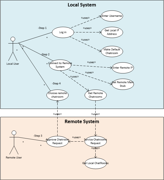
(Note: Example diagram does not show all the features described below.)
Features to be found in use case diagrams:
- Use Cases: represent tasks that are performed by the system. They represent the unified actions of whole collections of objects.
- Actors: represent the external entities that are interacting with the system. This is usually the user(s), but may be other system(s). When an actor has a relationship with a use case, it is said to be the "beneficiary" of that use case.
- Collaborations/Systems: represent a cooperative relationship between a collection of entities that produces the tasks described by one or more use cases. A collaboration essentially represents the implementation, as a whole, of the use case(s).
Relationships in a use case diagram
- Between Use Cases
- Communications: represents when one use case communicates information with another. Shown as a solid line with no arrowhead.
- Generalization: represents the relative difference in abstraction level between the two use cases. This is akin to the notion of inheritance in classes. One case is a more (or less) generalized version of the other, i.e. one use case is a concrete realization of the indicated abstract use case. Generalizations are represented by a solid line with a solid arrowhead where, just like inheritance in a UML class diagram, the arrow points from the realization to the abstraction. A common place to use generalizations are to represent different choices in processes that at situation dependent, e.g. if-else/switch statements, or different "flavors" of the same process. Some references:
- http://sce.uhcl.edu/helm/RationalUnifiedProcess/process/modguide/md_ucgen.htm
- http://www.batimes.com/articles/generalization-and-use-case-models-part-2.html
- Search for "use cases generalization"
- Dependencies
- General: represents the situation when one use case possibly depends on another for completion of its task. Dotted line with open arrowhead.
- Extends stereotype-- represents variant behavior of a use case. That is, the child use case is variation of the parent use case and is applicable in a different situations than the parent. The one case adds behavior to the other. Dotted line with open arrowhead. Recommend adding "
<<extends>>" stereotype label for clarity. Extends stereotypes are useful for expressing optionally executed behavior where the performing of the specified extension determined by certain conditions being met or by whom is invoking the use case. Extensions can also be useful for describing command or strategy executions. - Includes stereotype (aka "uses") -- represents a situation where one use case uses another use case in its entirety as part of its normal operation. Dotted line with open arrowhead. Recommend adding a "
<<uses>>" or "<<includes>>" stereotype label for clarity.
- Between Actors
- Inheritance -- represents an "is a" relationship, which is an abstraction difference, just as in classes. Shown as a solid line with a solid arrowhead.
- Dependency: One actor depends on another to do something. Shown as a dotted line with an open arrowhead.
- Communication: represents communication between actors. Shown as a solid line with no arrowhead.
- Between Actors and Use Cases
- Communicates: represents the transfer of information between an actor and a use case. This is the only way that an actor interacts with a use case. Shown as a solid line with no arrowhead.
- Between Collaborations and Use Cases
- Dependencies (dotted lines with arrowheads)
- General: a composition is composed of the indicated use cases. Dotted line with open arrowhead.
- Realizes (stereotype): represents the notion that a collaboration performs ("realizes") the referenced use case(s). Solid line with closed arrowhead. Recommend adding "
<<realizes>>" stereotype label for clarity.
- Dependencies (dotted lines with arrowheads)
REMEMBER: The (open) arrows between the individual uses cases in a use case diagram represent composition, not relative temporal execution!
When a use case has arrows (open arrowheads) pointing to other use cases, it means that use case is composed of the referenced use cases. It does NOT mean that one use case is executed and then the next is executed. If a temporal ordering of the use cases needs to be indicated, simply number the arrows to indicate the order in which the component use cases are executed in order to generate the overall use case. Convention is for the tasks to be ordered in temporal order from top to bottom in the diagram.
Use Case-driven System Block Diagrams
System block diagrams are the next developmental stage after creating Use Cases. These high-level modularizations of a system can be directly generated by simply organizing a well-constructed use case diagram.
For more information, see the Java Resources page on Use Case-driven System Block Diagrams.
Use Cases and Proof of System Architecture Design
Since use cases are fundamentally tied to the expression of and deliverance of the operations needed by users, use cases are a critical part of proving the viability of the design of a system's architecture.
End-to-End Integration
End-to-end integration means that the system is operational to the point where a user-driven operation can be traced through its associated use cases from one end of the system to another end of the system. For instance, in a distributed system, the operation should traverse through the use cases in one system, cross the network into another system and then traverse throught the use cases on that remote system.
Early end-to-end integration is a crucial part of the development process to show that the proposed architecture of the system will work for the desired use cases. For this reason, customers often demand to see end-to-end integration of the system at very early stages of the development process.
Use Case Coverage
Use case coverage refers to the ability to demostrate operationality of the system as traversals across all the use cases of the system. In order to show that a system has met its design requirements, the use case coverage must show that testing has demonstrated that all the use cases needed to meet the project requirements at that stage are operational. This is related to end-to-end integration in that use case coverage is essentially showing end-to-end integration through all the required use cases.
© 2020 by Stephen Wong
Source: https://www.clear.rice.edu/comp310/JavaResources/usecases.html
Posted by: remondinilanesays.blogspot.com

Posting Komentar untuk "Uml Use Case Diagram Relations"